Ogee diversion weir and headworks
A transparent preliminary redesign using the updated IMERG-based 50-year flood estimate. Flood passage, irrigation diversion, sediment control and energy dissipation are assessed as one headworks system.
1. Hydraulic design sequence
The new headworks is evaluated in engineering order: determine dependable irrigation supply, select operating pond level from canal FSL and head losses, check flood passage and afflux, size the intake and under-sluices, calculate the hydraulic jump and scour protection, then verify seepage, uplift and structural stability.
Flood-passing structure
- Adopt a design hydrograph and verify the peak Q50 = 195.2 m³/s.
- Survey channel width and bank elevations at the weir axis.
- Trial the ogee crest length and hydraulic design head.
- Check side contractions, approach velocity, tailwater submergence and resulting flood level.
Irrigation and sediment control
- Verify pond water level required for the 1.55 m³/s canal intake.
- Size regulator gates for operating heads and tailwater.
- Size under-sluices for required flushing duty and flood operating modes.
- Check sediment pocket, divide wall, trash rack, gate access and maintenance provisions.
2. Ogee crest — worked preliminary capacity check
A simplified ogee overflow relation for an initial trial is:
Q = C × L_eff × H_e^(3/2)
Here Q is discharge (m³/s), C is an SI discharge coefficient based on crest geometry and approach conditions, L_eff is effective crest length (m), and H_e is total energy head above the crest (m). C = 1.84 and L_eff = 45 m are trial assumptions, not verified site values.
H_e = [Q / (C × L_eff)]^(2/3) = [195.2 / (1.84 × 45)]^(2/3) = 1.77 m
Unit discharge q = Q / L_eff = 195.2 / 45 = 4.34 m³/(s·m)
Result: approximately 1.77 m of total head is required under the simplified free-overflow assumption. This is not the surveyed upstream flood water level; local approach-velocity head and tailwater conditions must be checked before converting energy head to water-surface elevation.
| Design quantity | Value / status |
|---|---|
| Adopted working 50-year flood | 195.2 m³/s (provisional IMERG-based scenario) |
| Trial overflow coefficient | C = 1.84 in SI units, pending crest-profile check |
| Trial effective overflow length | 45 m; river width, piers and sluice bays must be surveyed |
| Trial energy head over crest | 1.77 m for free overflow |
| Weir crest elevation and pond level | Not established by local cross section / canal FSL |
| Upstream and downstream flood levels at weir | Not yet extracted from HEC-RAS at the structure |
The overall river opening must be wider than an effective 45 m overflow length if separate sluice bays, intermediate walls, piers and abutments occupy width. The overflow length is not automatically the same as the channel width.
3. Canal and intake hydraulic capacity
The existing HARE irrigation design target is 1.55 m³/s. A representative lined trapezoidal canal trial is given for comparison, with a 1.20 m bottom width, 0.90 m flow depth, 1.5H:1V sides, Manning n = 0.018 and S = 0.00035.
A = y(b + zy) = 2.295 m²
P = b + 2y × sqrt(1 + z²) = 4.445 m
R = A/P = 0.516 m
Q = (1/n) × A × R^(2/3) × S^(1/2) = 1.535 m³/s
This trial is slightly below the target 1.55 m³/s, rather than exactly equal to it. At the same section and roughness, the theoretical slope needed for 1.55 m³/s would be about 0.0003568, subject to the actual canal longitudinal profile, drop locations and permissible velocity checks.
The head regulator requires a separate gate-flow rating and head-loss analysis, including sediment and trash-rack effects. It cannot be dimensioned uniquely from discharge alone.
4. Headworks components and their design checks
| Component | Required hydraulic or structural check |
|---|---|
| Under-sluices | Flushing discharge and gate rating for actual operating head; sediment transport, submergence and downstream protection |
| Divide wall | Alignment for effective low-level flushing and intake flow guidance; stability, scour and constructability |
| Head regulator | 1.55 m³/s operating rating, pond-to-canal head losses, gate dimensions, entrance velocity and sediment exclusion |
| Trash rack / sediment pocket | Head loss at clean and partially clogged states; sediment storage, flushing frequency and operator access |
| Stilling basin / glacis | Flow depth, incoming Froude number, conjugate depth, hydraulic-jump location and HEC-RAS tailwater compatibility |
| Cutoffs / floor / aprons | Foundation strata, seepage exit gradient, uplift, scour depth, slab thickness and launching apron |
| Stability | Sliding, overturning, base pressure, uplift, seismic loads where relevant and flood operating cases |
No foundation dimensions, stilling-basin length, riprap size or gate-opening size are presented as construction-ready without site measurements and hydraulic checks.
5. Headworks engineering figures
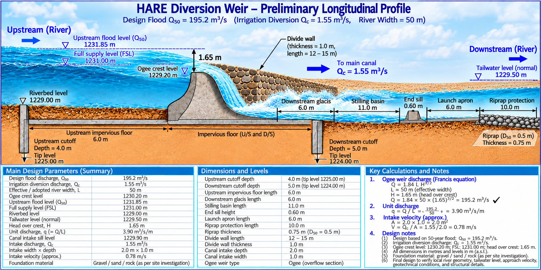
Figure placeholder for Chapter 8: Engineering Design Results. The final infographic must use verified geometry and hydraulic levels near the weir, not boundary-condition elevations from distant HEC-RAS locations.
Archived drawing: the image has not been found in /models/hec-hms/images/ on this installation. The new design page still works. The drawing will appear here once the existing gallery image has been uploaded.
6. What is required to finalize this design?
- Survey the local weir-axis river section, bank crest elevations and approach channel width.
- Extract a paired upstream and downstream HEC-RAS water-surface profile directly at the proposed structure, for the selected 195.2 m³/s design hydrograph.
- Confirm full supply level of each actual primary canal, intake connectivity and required operating pond level.
- Verify crest coefficient, contractions, ogee crest profile, free/submerged flow and upstream flood afflux.
- Dimension and check under-sluices, head regulator, sediment pocket, hydraulic-jump basin, floor, cutoffs and downstream protection.
- Complete geotechnical investigations, uplift/seepage calculations and structural stability before issue for construction.