5 Subbasins
S_1, S_2, S_3, S_4 and S_5 represent the hydrologically delineated drainage areas contributing to the Hare River.
The Hare River watershed was represented in HEC-HMS as five hydrologic subbasins connected through junctions and two routed river reaches to the Hare irrigation diversion site. The final modelled drainage area at the Hare Weir outlet is 162.035 km².
The basin model was constructed from the GIS-based watershed delineation. Terrain information from the Digital Elevation Model (DEM) was used to identify drainage direction, stream paths, subbasin boundaries and the river network draining toward the Hare diversion site.
The watershed was divided into five hydrologically connected subbasins, designated S_1 to S_5. Two principal river segments, R_1 and R_2, represent the routed sections of the main drainage system. Junction elements combine runoff generated in different parts of the watershed before the flow reaches the project outlet.
S_1, S_2, S_3, S_4 and S_5 represent the hydrologically delineated drainage areas contributing to the Hare River.
R_1 and R_2 represent the principal river sections through which upstream flood hydrographs are translated and attenuated.
Sink-1 represents the final HEC-HMS outlet at the Hare irrigation diversion and headworks site.
The final GIS delineation produced five subbasins with a combined area of 162.035 km². The largest unit is S_1, which accounts for almost half of the entire modelled watershed.
| Subbasin | Area (km²) | Share of Watershed | HEC-HMS Element |
|---|---|---|---|
| S_1 | 77.065 | 47.56% | Subbasin |
| S_2 | 25.498 | 15.74% | Subbasin |
| S_3 | 25.502 | 15.74% | Subbasin |
| S_4 | 13.533 | 8.35% | Subbasin |
| S_5 | 20.437 | 12.61% | Subbasin |
| Total | 162.035 | 100% | Hare Watershed |
The use of separate subbasins allows rainfall losses and runoff response to vary spatially rather than treating the entire Hare watershed as one lumped catchment.
Each HEC-HMS subbasin was assigned its own drainage area, weighted Curve Number and runoff lag. These parameters were derived from the GIS watershed analysis, land-use distribution, hydrologic soil grouping and drainage geometry.
| Subbasin | Area (km²) | Weighted CN | Final Lag (min) | Loss Method | Transform |
|---|---|---|---|---|---|
| S_1 | 77.065 | 78.26 | 118 | SCS Curve Number | SCS Unit Hydrograph |
| S_2 | 25.498 | 78.94 | 76 | SCS Curve Number | SCS Unit Hydrograph |
| S_3 | 25.502 | 75.63 | 65 | SCS Curve Number | SCS Unit Hydrograph |
| S_4 | 13.533 | 74.62 | 52 | SCS Curve Number | SCS Unit Hydrograph |
| S_5 | 20.437 | 78.60 | 62 | SCS Curve Number | SCS Unit Hydrograph |
Two principal reaches were retained in the HEC-HMS basin model. R_1 is the longer upstream routing reach, while R_2 forms the shorter downstream reach immediately upstream of the Hare diversion area.
Reach lengths and longitudinal slopes were obtained from the GIS drainage network and DEM-derived elevation characteristics.
| Reach | Length (m) | Length (km) | Average Slope | Adopted Manning n | Routing |
|---|---|---|---|---|---|
| R_1 | 10,377.24 | 10.377 | 0.112458 | 0.050 | Muskingum |
| R_2 | 4,745.09 | 4.745 | 0.033298 | 0.040 | Muskingum |
R_1 is approximately 10.38 km long, whereas R_2 is approximately 4.75 km. The substantially steeper average gradient of R_1 reflects the upper part of the drainage system, while the lower reach becomes less steep as the river approaches the Hare irrigation area.
HEC-HMS junction elements were used to combine runoff from different portions of the watershed and to transfer the resulting hydrograph into the downstream routing reaches.
Upstream Subbasins → J_1 → R_1 → J_2 → R_2 → Hare Weir / Sink-1
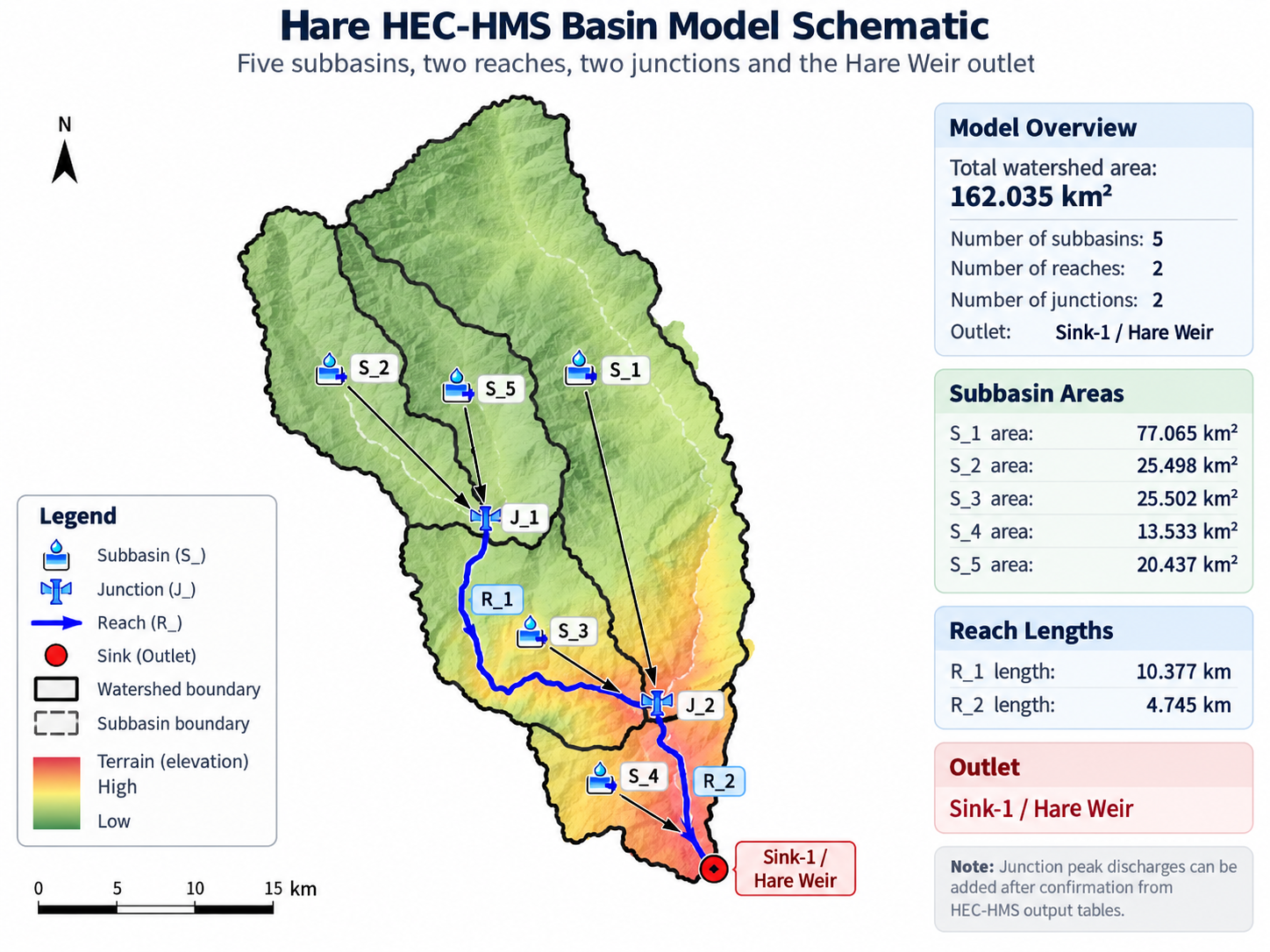
Subbasins S_2 and S_5 contribute to the upstream junction J_1. Their combined hydrograph is routed through R_1 toward the lower part of the watershed.
Additional subbasin runoff enters the main drainage network as represented by the final HEC-HMS basin schematic. The routed upstream flow then passes through J_2 and R_2 before reaching the project outlet.
At the downstream end of the model, runoff from S_4 is combined with the routed flow arriving through R_2 before the total hydrograph is reported at Sink-1.
The final model outlet is represented in HEC-HMS by Sink-1. This location corresponds to the Hare irrigation diversion / weir site and was selected because the main purpose of the hydrologic model is to estimate the flood hydrograph reaching the proposed or reconstructed headworks.
Sink-1
HEC-HMS terminal element representing the Hare project outlet.
162.035 km²
Total drainage area represented by subbasins S_1 to S_5.
Hare Weir / Headworks
Design-flow extraction point for hydraulic assessment of the diversion works.
Discharge Hydrograph
Provides peak discharge, timing of peak, runoff volume and the complete flood hydrograph.
The basin model was developed from spatial data rather than by manually assigning arbitrary drainage areas. GIS processing provided the basic geometric framework required by HEC-HMS.
| Model Information | Derivation / Use |
|---|---|
| Watershed boundary | Delineated from the DEM using the Hare diversion site as the downstream control point. |
| Subbasin boundaries | Derived from terrain-controlled drainage divides. |
| Subbasin areas | GIS-calculated areas for S_1 to S_5. |
| Drainage network | Derived from DEM flow direction and flow accumulation. |
| Reach lengths | Measured along the GIS-derived main river network. |
| Reach slopes | Derived from the elevation change along each river reach. |
| Land use | Used with hydrologic soil information to calculate weighted Curve Numbers for each subbasin. |
| Outlet | Positioned at the Hare Weir / irrigation headworks. |
The figure below presents the final HEC-HMS basin-model configuration for the Hare River watershed. It shows the five subbasins S_1–S_5, the two junctions J_1 and J_2, routed reaches R_1 and R_2, and the downstream Sink-1 / Hare Weir outlet.
The schematic also summarizes the drainage area of each subbasin and the lengths of the two principal routed river reaches. Together, these elements define how runoff generated throughout the 162.035 km² watershed is combined and routed toward the Hare irrigation headworks.
| Total Watershed Area | 162.035 km² |
|---|---|
| Subbasins | 5 — S_1, S_2, S_3, S_4, S_5 |
| Largest Subbasin | S_1 — 77.065 km² |
| River Reaches | 2 — R_1 and R_2 |
| R_1 Length | 10.377 km |
| R_2 Length | 4.745 km |
| Junctions | J_1 and J_2 |
| Routing Method | Muskingum |
| Downstream Element | Sink-1 |
| Engineering Outlet | Hare Weir / Irrigation Headworks |
This basin configuration forms the spatial framework for the HEC-HMS rainfall-runoff simulations. Design precipitation is applied to each subbasin, rainfall excess is transformed into direct runoff, the resulting hydrographs are combined and routed through the river network, and the final design hydrograph is obtained at the Hare Weir.